- 您现在的位置:买卖IC网 > Sheet目录3841 > DSPIC30F1010-30I/SP (Microchip Technology)IC DSPIC MCU/DSP 6K 28DIP
dsPIC30F Flash Programming Specification
DS70102K-page 22
2010 Microchip Technology Inc.
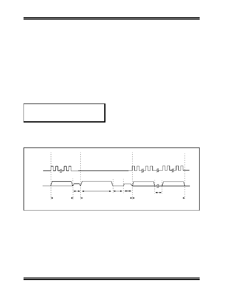
clocked out. The programmer can begin to clock out
the response 20
μsec after PGD is brought low, and it
must provide the necessary amount of clock pulses to
receive the entire response from the programming
executive.
Once the entire response is clocked out, the
programmer should terminate the clock on PGC until it
is time to send another command to the programming
executive. This protocol is illustrated in Figure 7-2.
7.3
SPI Rate
In Enhanced ICSP mode, the dsPIC30F operates from
the fast internal RC oscillator, which has a nominal
frequency of 7.37 MHz. This oscillator frequency yields
an effective system clock frequency of 1.84 MHz. Since
the SPI module operates in Slave mode, the
programmer must limit the SPI clock rate to a
frequency no greater than 1 MHz.
Note:
If the programmer provides the SPI with a
clock faster than 1 MHz, the behavior of
the programming executive will be
unpredictable.
7.4
Time Outs
The programming executive uses no Watchdog Timer
or time out for transmitting responses to the
programmer. If the programmer does not follow the flow
control mechanism using PGC, as described in
col”, it is possible that the programming executive will
behave unexpectedly while trying to send a response
to the programmer. Since the programming executive
has no time out, it is imperative that the programmer
correctly follow the described communication protocol.
As a safety measure, the programmer should use the
command time outs identified in Table 8-1. If the
command time out expires, the programmer should
reset
the
programming
executive
and
start
programming the device again.
FIGURE 7-2:
PROGRAMMING EXECUTIVE – PROGRAMMER COMMUNICATION PROTOCOL
1
2
15 16
1
2
15 16
PGC
PGD
PGC = Input
PGC = Input (Idle)
Host Transmits
Last Command Word
PGD = Input
PGD = Output
P8
1
2
15 16
MSB X X X LSB
1
0
P9b
P10
PGC = Input
PGD = Output
P9a
Programming Executive
Processes Command
Host Clocks Out Response
P11
发布紧急采购,3分钟左右您将得到回复。
相关PDF资料
PIC24FJ64GB002-I/ML
IC MCU 16BIT 64KB FLASH 28QFN
52746-1270
CONN FFC 12POS .5MM R/A ZIF SMD
TS80C31X2-MCE
IC MCU 8BIT 40/20MHZ 44-VQFP
52746-0870
CONN FFC 8POS .5MM R/A ZIF SMD
PIC24FJ128GA008-I/PT
IC PIC MCU FLASH 128K 80TQFP
PIC16F737-I/SP
IC PIC MCU FLASH 4KX14 28DIP
PIC18F86K22-I/PTRSL
MCU PIC 64K FLASH XLP 80TQFP
PIC16C63A-04I/SP
IC MCU OTP 4KX14 PWM 28DIP
相关代理商/技术参数
DSPIC30F1010-30I/W
制造商:MICROCHIP 制造商全称:Microchip Technology 功能描述:28/44-Pin High-Performance Switch Mode Power Supply Digital Signal Controllers
DSPIC30F1010AT-20E/PF
制造商:MICROCHIP 制造商全称:Microchip Technology 功能描述:High-Performance, 16-Bit Digital Signal Controllers
DSPIC30F1010AT-20I/PF
制造商:MICROCHIP 制造商全称:Microchip Technology 功能描述:High-Performance, 16-Bit Digital Signal Controllers
DSPIC30F1010AT-30I/PF
制造商:MICROCHIP 制造商全称:Microchip Technology 功能描述:High-Performance, 16-Bit Digital Signal Controllers
DSPIC30F1010BT-20I/PF
制造商:MICROCHIP 制造商全称:Microchip Technology 功能描述:High-Performance, 16-Bit Digital Signal Controllers
DSPIC30F1010BT-30I/PF
制造商:MICROCHIP 制造商全称:Microchip Technology 功能描述:High-Performance, 16-Bit Digital Signal Controllers
DSPIC30F1010CT-20I/PF
制造商:MICROCHIP 制造商全称:Microchip Technology 功能描述:High-Performance, 16-Bit Digital Signal Controllers
DSPIC30F1010CT-30I/PF
制造商:MICROCHIP 制造商全称:Microchip Technology 功能描述:High-Performance, 16-Bit Digital Signal Controllers